
Weld Symbols on Drawings Say More Than Where the Weld Goes
A fillet symbol with no size is an open question. The fabricator has to guess the leg length, and the guess may not match what the design needs.
Weld callouts compress a lot of instruction into a small mark. Written fully, they tell the fabrication shop the joint type, the size, the side, the finish, and the procedure. Left incomplete, they push those decisions onto whoever is at the bench.
The Anatomy of a Weld Symbol
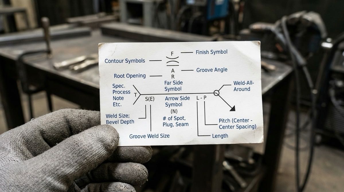
North American drawings follow AWS A2.4, Standard Symbols for Welding, Brazing, and Nondestructive Examination. The symbol is built on three parts: a reference line, an arrow, and an optional tail.
The arrow points to the joint. The reference line carries the weld symbol itself. The tail, when present, holds notes such as the process or procedure reference.
Which side of the reference line the symbol sits on matters. A symbol below the line applies to the arrow side of the joint. A symbol above the line applies to the other side. Putting it on the wrong side puts the weld on the wrong face of the part.
Where the Numbers Go on Common Weld Types
Each weld type has its own symbol shape, and the dimensions sit in fixed positions around it. This table covers the three types a fabricator sees most often.
| Weld Type | Symbol | Left of the Symbol | Right of the Symbol |
|---|---|---|---|
| Fillet | Right triangle | Leg size | Length, and pitch if intermittent |
| Groove | Square, V, bevel, U, or J shape | Groove depth, with effective throat in parentheses | Length, and pitch if intermittent |
| Plug or slot | Rectangle | Hole or slot size | Pitch between welds |
Groove welds add a few more entries. Root opening goes inside the symbol and groove angle goes beside it. A missing number on any of these leaves the joint prep undefined, and joint prep drives how the part fits up.
Reading One Complete Callout
Take a fillet symbol on the arrow side with 1/4 to its left and 2-6 to its right. The 1/4 is the leg size, in inches. The 2-6 means each weld is 2 inches long, spaced 6 inches apart center to center. Read together, the callout asks for an intermittent fillet weld, not a continuous bead.
Now take a V-groove symbol with a root opening noted inside it and a groove angle beside it. That callout describes joint preparation before any weld metal goes in. The fabricator cuts and fits the edges to those numbers, then welds the joint.
Both examples show the same discipline. Every number has a fixed position, and every position answers one question. Move a number, and the question it answers changes.
Choosing Between Fillet and Groove Welds
The symbol follows the joint. Fillet welds join surfaces that meet at an angle, such as a tee or a lap. Groove welds join edges that meet face to face, as in a butt joint, and they require edge preparation first.
That choice belongs to the design, not the shop. A fillet weld costs less to prepare, while a groove weld can carry more load through the joint. A drawing that names the wrong type for the loading forces a change order later, so the decision should be made with the load path in mind.
Continuous or Intermittent Welds
Intermittent welds put less heat into the part, which can reduce distortion on long, thin members. They also leave gaps that can trap moisture on parts exposed to weather or washdown. Continuous welds seal the joint but add more heat and more weld metal.
The drawing should say which one the part needs, and why when the reason is not obvious. A seal or cleanliness requirement is a different instruction than a strength requirement, and the shop plans the weld sequence differently for each.
Supplementary Symbols That Change the Job
Small marks on the reference line carry large instructions. A circle at the junction of the arrow and reference line means weld all around. A flag means the weld is made in the field, not in the shop.
Contour symbols describe the finished face of the weld: flat, convex, or concave. A letter beside the contour names the finishing method, such as G for grinding or M for machining. That letter matters more than it looks, because it tells the shop whether the weld bead stays as is or gets removed flush.
What the Tail Carries
The tail is where a drawing references the welding process, the welding procedure specification, filler material, or a general note. If the tail is empty, those choices default to the fabricator.
That default may be fine for non-critical brackets. For a structural frame, a pressure-related part, or an assembly with a documentation requirement, the procedure reference belongs on the print or in the purchase order. Leaving it out is a buyer decision, not a shop oversight.
Inspection Symbols Share the Same Line
AWS A2.4 covers more than welds. It also defines symbols for nondestructive examination, which tell the inspector the method, the extent, and sometimes the frequency of testing on a joint.
When an examination requirement belongs to the part, it should be on the drawing, not assumed. A weld that was never marked for examination will not be examined, and a weld that was marked will need documentation to show it passed.
Callout Mistakes That Cause Rework
Most weld rework traces back to a handful of drawing gaps. They are easy to prevent and expensive to find after the assembly is welded.
- A fillet callout with no size, and no general note that sets one
- The symbol placed on the wrong side of the reference line
- Weld all around used on a joint where one face cannot be reached
- No process or procedure reference on a part that needs one
- A contour call with no finish letter, leaving the grind or machine decision open
Each one costs seconds to fix on the print. Each one costs hours after the weld is down.
AWS and ISO Symbols Are Not Interchangeable
Drawings from international customers may follow ISO 2553 instead of AWS A2.4. The two systems share the idea of a reference line and arrow, but ISO adds a second, dashed line and places the symbol differently.
A shop used to one system can misread the other. If a print arrives without a stated standard, ask which one governs before cutting material.
Welded Assemblies That Get Machined After Welding
Many fabricated parts are not finished at the weld. A welded base or frame often moves on to machining, where mounting faces and bores must land in tolerance.
Weld heat distorts steel, so the welding sequence and any stress-relief step affect how much material is left to machine. A drawing that calls out a machined finish on the weld, or a machining allowance on the fabricated surface, gives the shop what it needs to plan that handoff. Metal fabrication with welding, cutting, and assembly and finish machining work best when planned as one job.
How FM Machine Handles Weld Callouts on Fabricated Assemblies
FM Machine Co. has provided precision CNC machining and fabrication from Akron, Ohio since 1963. Welded assemblies can move straight from fabrication to finish machining under one quality system, with 100% parts inspection on machined features.
- Confirm the governing standard, AWS A2.4 or ISO 2553
- Put size, side, and length on every weld callout
- Reference the procedure in the tail when the part requires one
- Call out machining allowance where welded surfaces will be finished
A weld symbol that leaves out size, side, or procedure hands design decisions to the shop floor. If your next project requires tight tolerances, documentation, and a shop you can count on, FM Machine is ready to take a look. Request a quote and let’s talk specs.